
If you own a diesel car chances are you know about issues caused by unsupervised DPF burnouts. Knowing when DPF soot is going to be burned out and what is the current status of burning is crucial for keeping many vehicle components in good condition.
Existing solutions for monitoring DPF
How can you monitor it then? There are few ways:
- Having car that can display DPF information by default. Unfortunately most vehicles don’t provide any information about DPF on dashboard (does anybody know why?).
- LED burnout indicator. When burning soot many cars turn on additional electronic devices to create higher load on engine. One of such devices is mirror heater. You can simply install LED by attaching it to the same circuit mirror heater use. When soot is being burned, mirror heats and LED turns on. The drawback of this solution is we don’t get to know DPF fill percentage, burning status or kms since last regeneration. If we don’t know the DPF fill percentage we can’t predict when the process is going to trigger. It can therefore happen in the middle of busy traffic downtown which would suck.
- Use OBD scanner and smarphone app like OPL DPF MONITOR. This solution provides all the information we need. The drawback is we have to turn on app each time, connect to bluetooth and mount the phone in visible place. Whole process is too tedious for me to do every time. On top of that screen is active all the time which drains a lot of battery. We also can’t use phone’s bluetooth for other purposes (playing music etc.).
Arduino + OBD = <3
We can however replace smartphone with arduino to display results on LCD. It will turn on, connect and turn off automatically when entering and leaving the car.
The solution I developed is for Opel Insignia but should work for any car. I tested few different combination of bluetooth modules and OBD readers. Some of them were either unable to read Insignia PIDs (these are non standard OBD codes), or they were unable to communicate with each other over bluetooth. Pay extra attention to what components you buy.
We’re gonna need:
- Arduino Nano
- OBD reader - iCar2 Vgate Bluetooth 3.0 (many cheap ELM327s do not work)
- Bluetooth module - HC-05 v3 (v2 won’t work)
- 2x16 LCD with i2c converter
- 3d printer (optional)
Arduino uses HC-05 bluetooth module to communicate with OBD reader. Results are displayed on LCD which is also connected to arduino.
Wiring
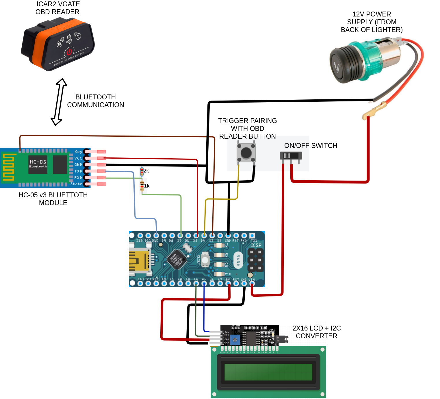
HC-05 bluetooth module
Communication between arduino and HC-05 module is done over UART. We don’t want to use hardware serial (RX,TX pins) -
afaik if we did we wouldn’t be able to debug using PC. Since we don’t need super high speed software serial is more than enough so we can use any digital pin.
Pin 10 and 7 were therefore chosen. Since HC-05 expects 3.3v to be sent to it’s RX pin we add voltage divider composed of 2k and 1k resistors
to reduce arduino’s digital output from 5v to 3.3v.
We also need to be able to reset and reconfigure HC-05 using arduino. This is neccessary in order to pair with new OBD reader device. HC-05 will then be unable to connect with it and will need reconfiguration.
In order to boot HC-05 into configuration mode it’s 34pin has to be pulled HIGH (5v) and the module has to be reset. We use arduino digital pin 5 and 4 for that purposes.
Bluetooth configration button
The purpose of button is to allow user to trigger HC-05 configuration. It’s required after new OBD reader is used or existing OBD reader was used with different device.
On/off switch
Even though the device will automatically turn itself on and off when user enters/leaves the car (it’s using same circuit as 12v lighter socket) it’s a nice feature to have.
LCD
2x16 LCD alone requires a lot of wires to work with arduino. It’s easier to solder i2c converter to it and just connect 2
wires to arduino.
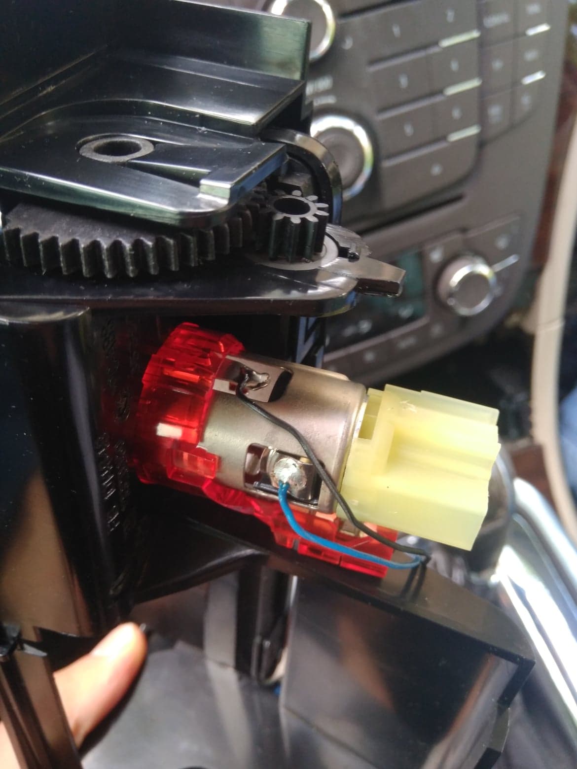
Lighter socket power supply
In my opinion 12v lighter socket is the best source of power. It will turn on when ignition is turned on. It will turn off when user leaves car (opens door after turning off engine). In case of Insignia it is also in a very convenient place. Next to the lighter socket there is handy hole that we can use for placing and hiding guts of our device. It’s very easy to solder directly to lighter socket on the back where it is not visible. You will however need to disassemble panel that holds it in place and unplug the lighter socket.
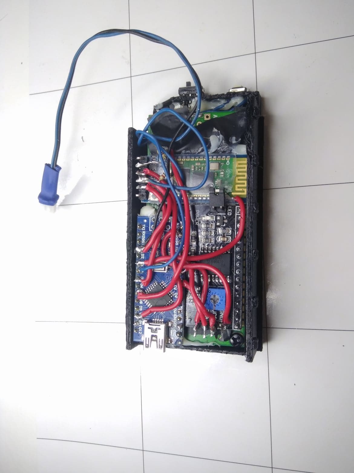
Plastic case
You can download 3d model here. It will lock in nicely into the hole that is next to the lighter socket in Opel Insignia. If you dont have a 3d printer you can buy/find existing case and cut hole for lcd.
Coding
Click here to get full code from github.
We need to pull 3 types of data from a car:
- DPF regeneration status. 0 if not burning. 1-255 if burning (percentage completed).
- DPF fill percentage (0-100).
- Distance since last burnout (in kms).
In case of Opel Insignia these are following PIDs - (223274, 223275, 223277).
Finding PID codes for your car might be challenging. Personally I couldn’t find anything online.
I ended up sniffing what commands are sent by OPL DPF MONITOR android app.
I used a method describere here to sniff bluetooth traffic.
PID is just a command that is understood by at least one of the car’s module.
Because above PIDs are not standardized we also need to provide header. Header is
a destination for a PID command to be issued. This tells OBD reader to send it to specific car’s module.
In case of Insignia it is 7E0 which is just an engine computer.
To retrieve data we therefore need to first set header to 7E0:
vgate.sendCommand("AT SH 7E0")
Afterwards we can query PIDs:
int32_t getRegenerationStatus() {
  return queryVgate(0x22, 0x3274);
}

int32_t getKmsSinceDpf() {
  return queryVgate(0x22, 0x3277);
}

int32_t getDpfDirtLevel() {
  return queryVgate(0x22, 0x3275);
}
Luckily ELMduino library handles all the details when it comes to communication with OBD reader. Just make
sure you use newest version. It seems to be actively developed.
I personally found one edge case and submitted PR - maintainer approved and merged it the same day.
To display values on the lcd simply use LiquidCrystal_I2C library like so:
lcd.clear();
lcd.setCursor(0,0);
String message = "LAST: ";
message = message + kmsSinceDpf + "KM";
lcd.print(message);
lcd.setCursor(0,1);
message = "FILL: ";
message = message + dirtLevel + "%";
lcd.print(message);
HC-05 auto-configuration
In order to pair HC-05 module with OBD reader it needs to be launched in configuration mode. This is done by either pressing and holding button on the HC-05 module or setting pin 34 to high when powering. This project makes the process automatic when “TRIGGER PAIRING WITH OBD READER BUTTON” is held. It will set pin 34 to high and reset HC-05 module. Afterwards arduino will send all the necessary pairing commands, set pin 34 to low and reset HC-05 again. Afterwards it will launch into normal mode and start connecting to paired OBD reader every time it is powered on. Just make sure to replace your OBD reader bluetooth address in the code:
sendCommand("AT+BIND=86DC,3D,ABF7F1");
sendCommand("AT+PAIR=86DC,3D,ABF7F1,20",10000L);
sendCommand("AT+LINK=86DC,3D,ABF7F1",10000L);
Don’t worry if AT+INIT command returns ERROR. It’s “normal” for v3 module according to online resources :).
